Watermota SeaWolf, circa. 1972
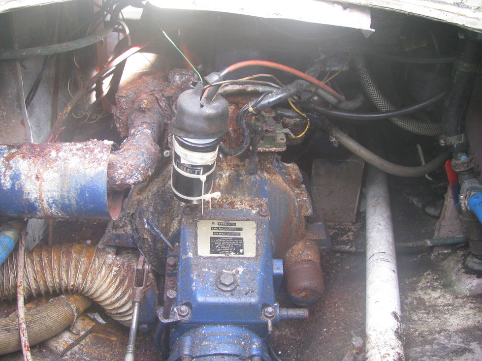
The goal - to replace this:
Watermota SeaWolf, circa. 1972
with this:
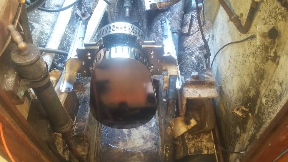
Thoosa 7000HT, circa. 2020. Click link for
more details and documentation.
For the parts list, see parts
(OK, without the dirt either...)
The motor is a Thoosa 7000HT, rated for 7kW continuous output, running on 48V DC. It is reversible, and capable of some "regenerative braking" when under sail.
The batteries are ReLiOn RBGC248V LiFeO4 (LiPo) golf cart batteries, rated 30AH at 48V, with integrated battery management electronics and CANbus interconnect. Two batteries in parallel is the minimum to run the motor at full speed.
For shore power, there is a GX4820 48V 20A industrial charger.
For solar power, there will be ten Solarparts semi-flexible panels, nominal 100W but actually rated 74W at normal operating temperature. There is a Smart Solar 150/70 MPPT charge controller with a remote display. The panels produce 16.5V at the maximum power point, the batteries need at least 55V to charge, so there will be two strings of five panels each, producing about 80V.
Sketch of motor installation (PDF)
Click thumbnails for larger image
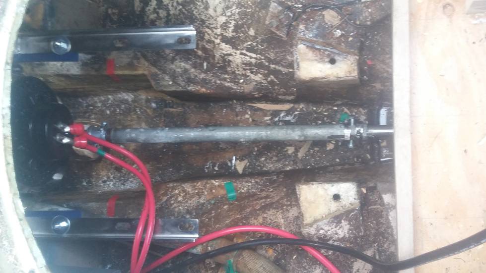
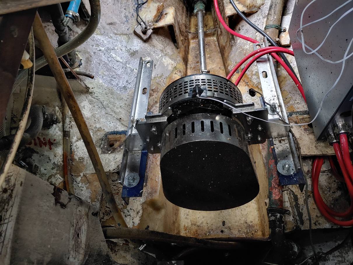
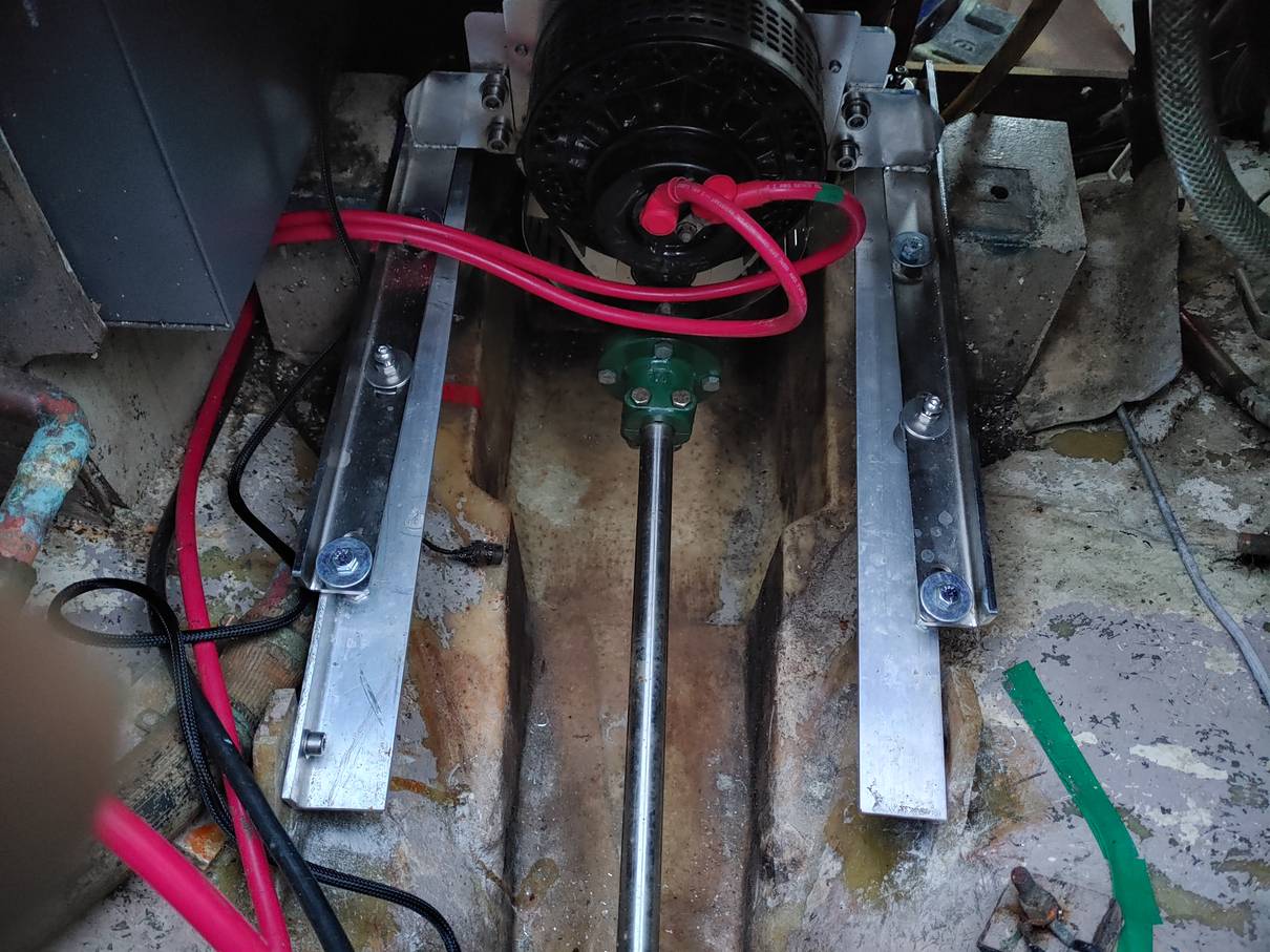
 Motor with Mk 1 temporary shaft extension
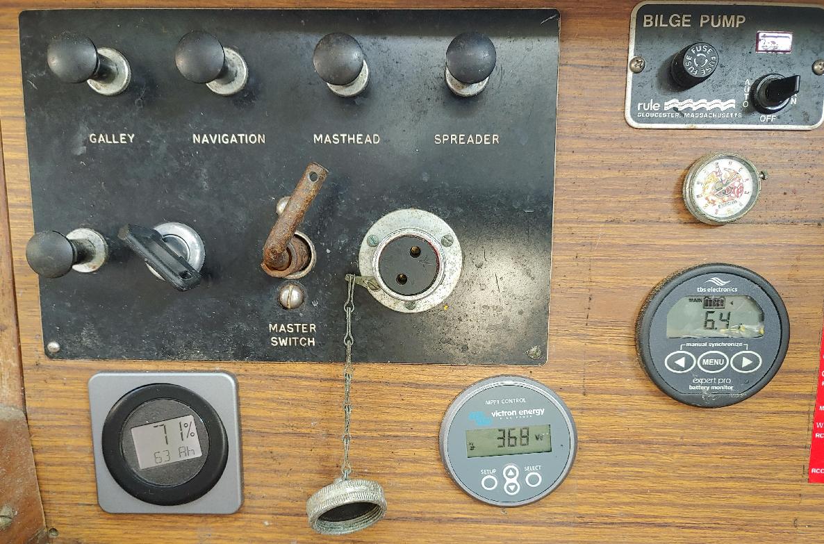
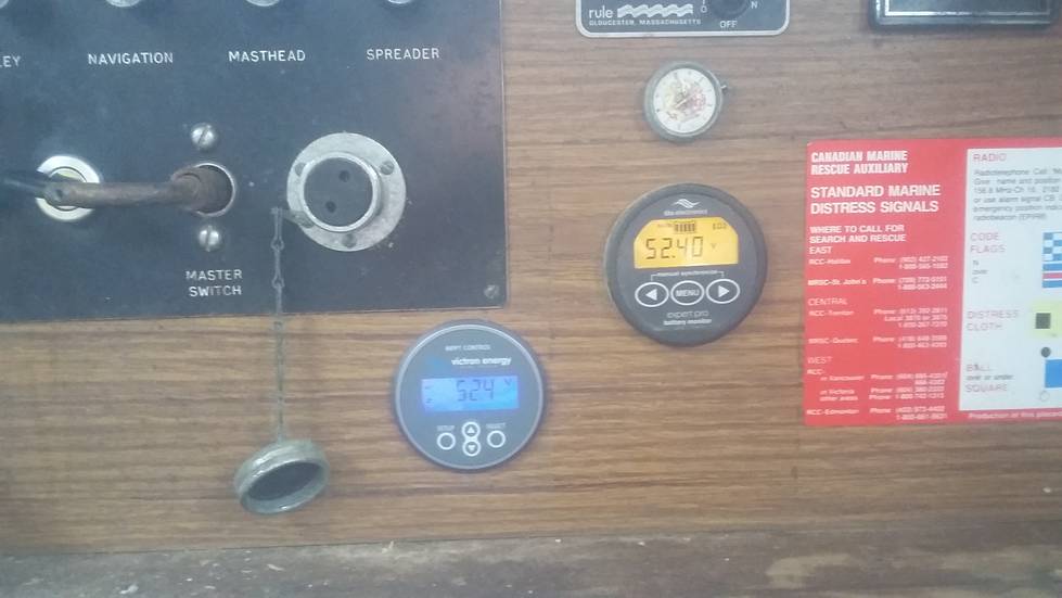 New instruments - motor and solar monitors
 New throttle, keyswitch and monitor
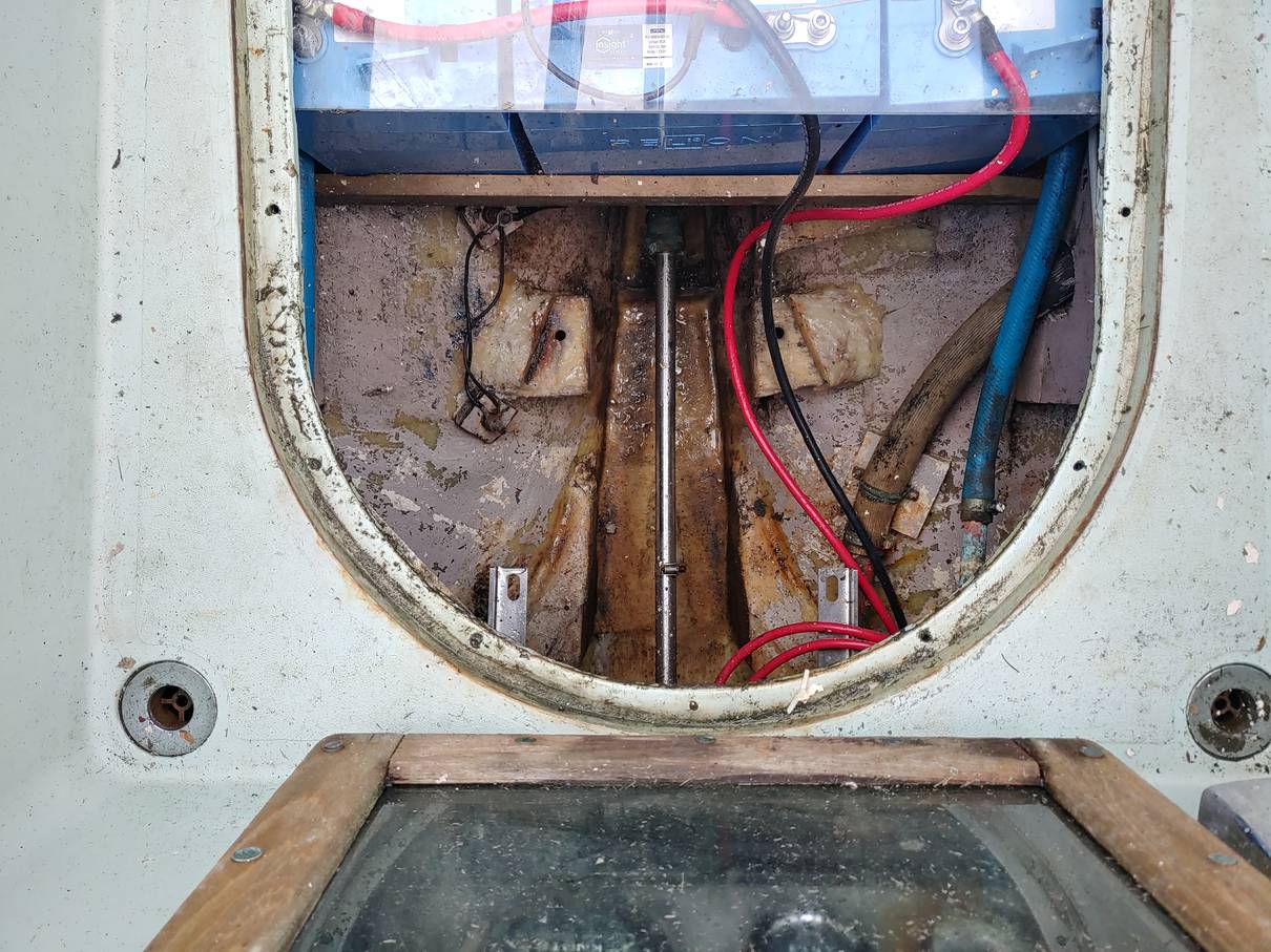
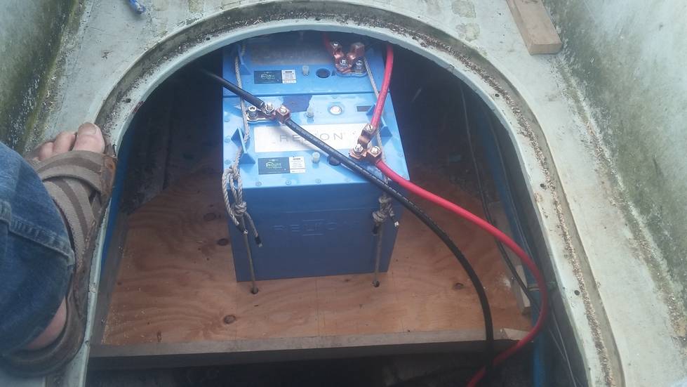 First two batteries under cockpit sole
 Solar charge controller
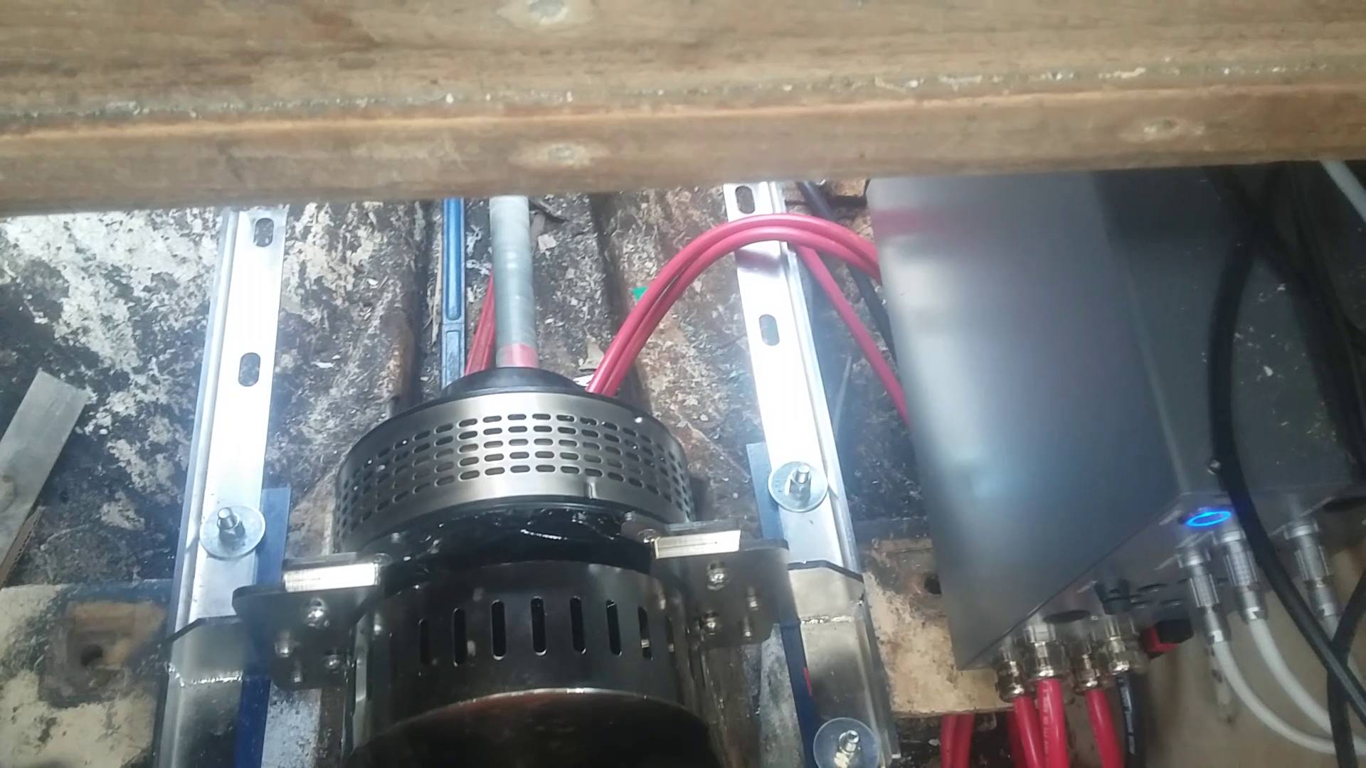
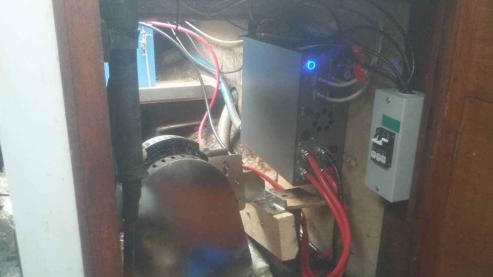 Motor, controller, circuit breakers
The starter motor on the original Watermotor jammed in 2020, but I was able to remove it, take it apart and free it up. This year it did the same thing, but I'd had enough - I removed the entire mess and temporarily fitted the electric motor while at the mooring - lowered the engine onto my little catamaran with the boom, took it to shore and dragged it up the beach with my truck.
My initial idea was to make a temporary propeller shaft extension, just good enough to let me motor out to sea, and sail to a boatyard. My first attempt worked - everything ran, I was able to move under electric power (at least, after removing a heavy weed growth from hull, propeller and rudder), but the plastic broke when I applied more throttle to counter a current. Fortunately, there was favourable wind so I sailed back to the mooring. The second temporary extension was in steel pipe, but I had some wobble which would probably have damaged the stern tube if I'd gone very far. The current plan is to get a complete new shaft and coupling fabricated, which will take at least a couple of weeks, then careen Alastor to fit the new shaft. Then I can proceed to the boatyard in a more normal fashion for haul-out and painting.
I tried to remove the propeller at the mooring, using SCUBA gear. I'd made up a custom prop puller, but nothing doing. So to plan B - remove the shaft together with propeller, then replace it temporarily with the original bronze shaft I still have from around 1990 to keep the water out. Doing that in situ would probably have worked, pushing the old shaft out from inside with the even older one, but it was easier and less risky to careen the boat and do it out of the water. I managed to finally get the prop off the shaft with the aid of a heat gun (bronze has a thermal expansion coefficient of 12 compared to 7 for steel) in conjunction with the prop puller.
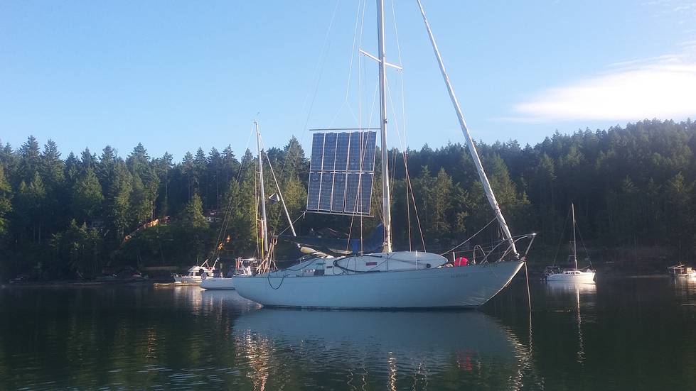 Solar panels temporarily mounted on mainsheet slide. The final plan is
to fit a second track alongside the mainsail track so I can hoist both at once,
or at least not have them interfere with each other.
Solar panels temporarily mounted on mainsheet slide. The final plan is
to fit a second track alongside the mainsail track so I can hoist both at once,
or at least not have them interfere with each other.
 Mk II temporary shaft extension
 Mk II motor mounts, replacing Mk 1 wooden ones
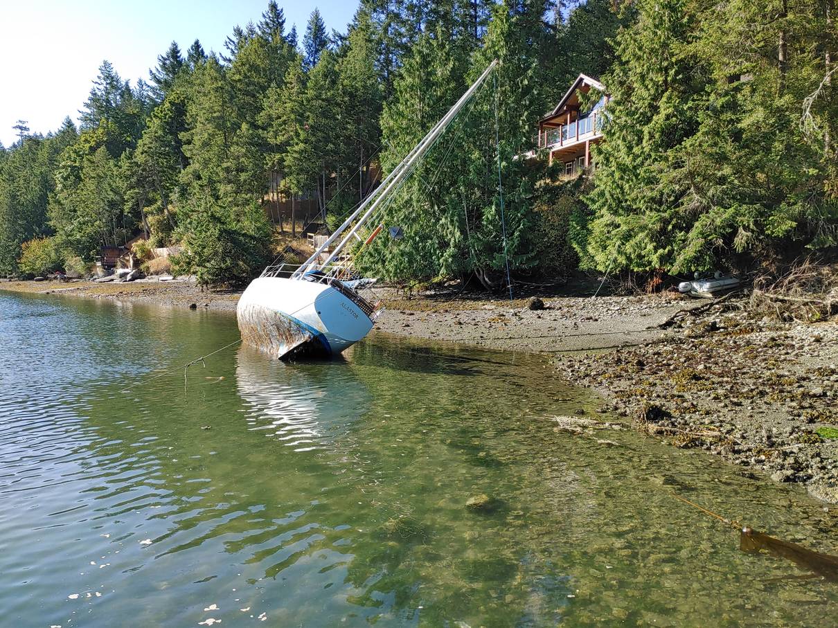 Careening Alastor in Horton Bay to swap propeller shafts.
 The propeller puller
The original Watermota gearbox had a 1 inch shaft, same as the propeller, and a keyed flange secured with a nut (and really well jammed on, almost an interference fit). The propeller shaft had a mating keyed flange, secured against reverse thrust with a couple of bolts bearing on dimples in the shaft. Dafoe's new flanges are better engineered, with an alignment ring between the flanges, and secured with through bolts that engage with indents machined in the shaft. The new longer propeller shaft had the indents already in place, but they didn't want to touch the Thoosa shaft, saying it might be hardened or something. I managed to carve the indents with a file, and using a twist drill as a ream to get the right shape. I also lapped the flanges onto both shafts using a bit of polishing compound, as they were really stiff - I didn't want to have to bang them in place with a hammer.
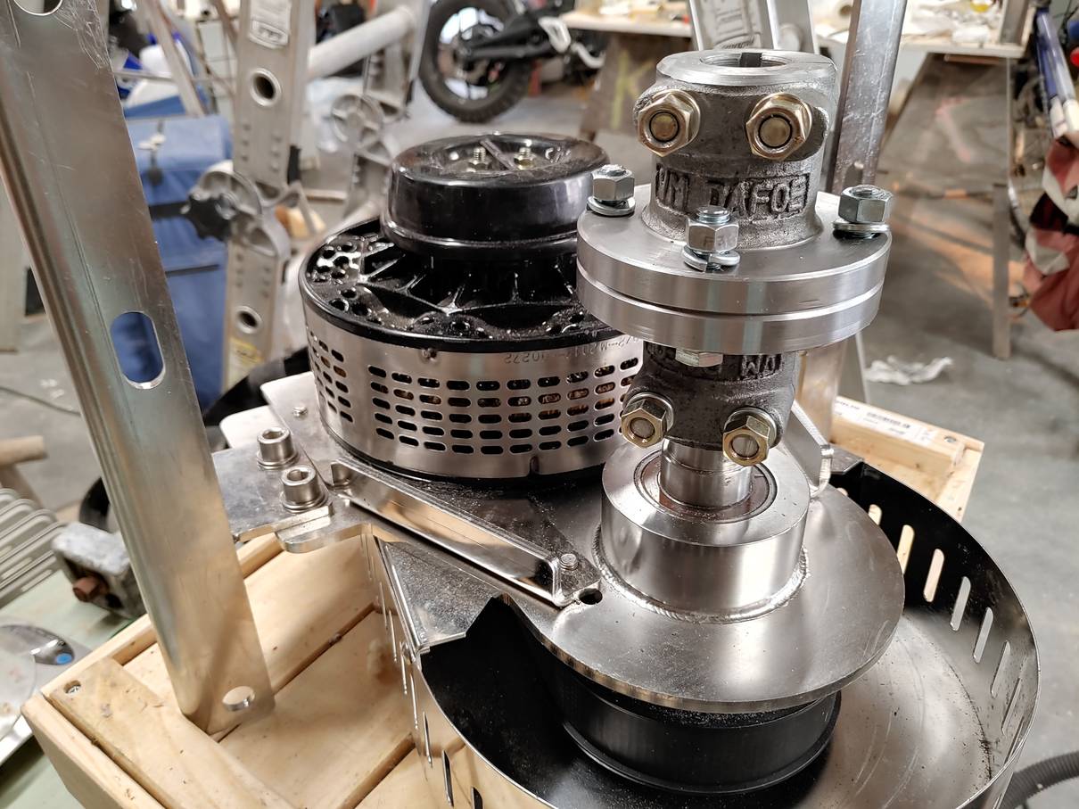 Thoosa motor with new coupling flanges
 Thoosa motor with indents filed in shaft
My mast hardware that had been on order for a couple of months arrived, so I was able to fit that. It was made to take countersunk bolts but I wanted to use pop-rivets, so I ground a twist drill flat and used that to machine the bolt holes to a cylindrical shape.
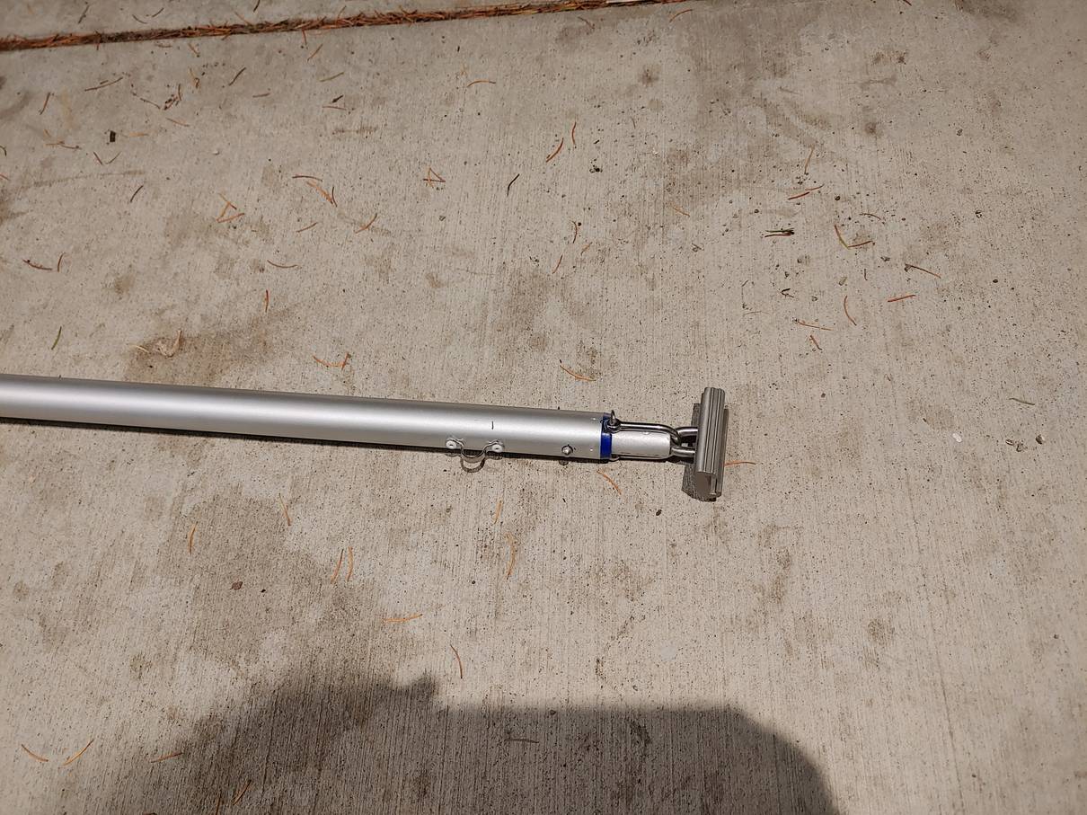
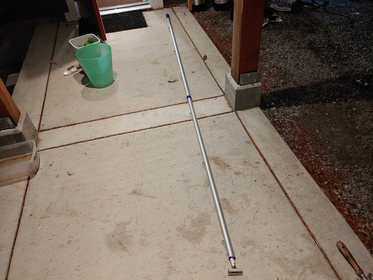
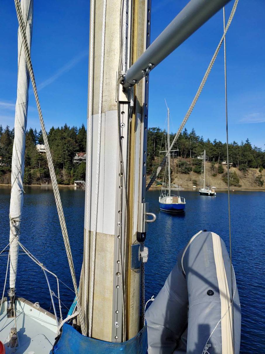
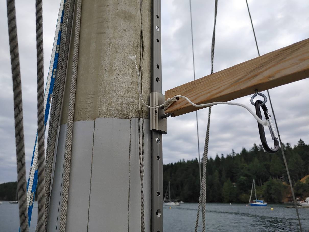 Solar panel track with temporary spar.
I contrived to thread a cable from the engine compartment under the portside bunk and up the mast, for the solar panels. There are two strings of five panels each, sharing a common negative wire. The two strings are in parallel, each with a separate circuit breaker. That gives a suitable voltage to feed the charge controller - it has to be somewhat more than the battery voltage (50V), but less than the maximum allowed (145 volts). Each panel gives 16V at maximum power point so that's 80V per string. This arrangement also lets me hoist half of the panels and still charge. When drilling the hole in the mast, I found I'd gone into an internal conduit or pipe that contains the cables for the masthead antenna and light. I hadn't realized that was there, but it worked out OK in the end. I was able to run a fish tape down and out the bottom of the mast, and pull a steel wire through, and then the actual cable, well lubricated with washing-up liquid.
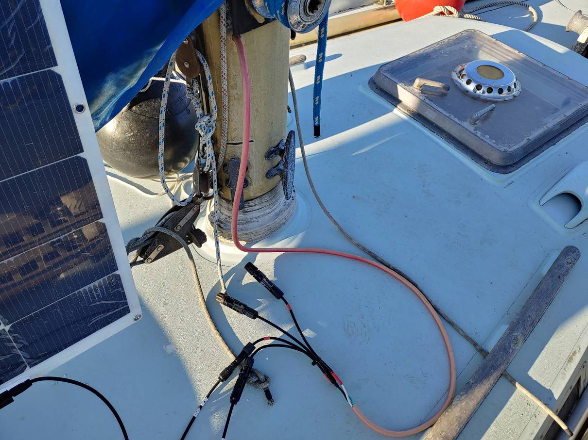 Solar power cable in mast, with connectors for two strings.
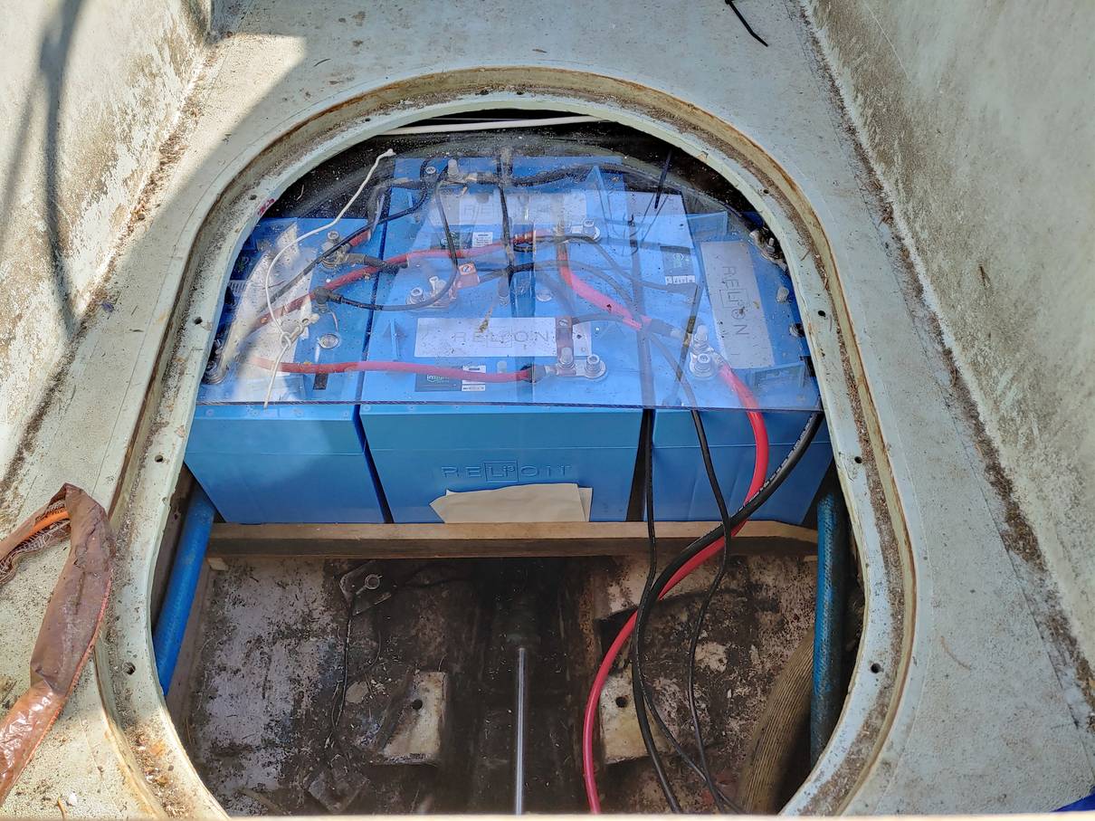 Final arrangement of four batteries in parallel, 120Ah at 50V.
The batteries are lithium iron phosphate, with integral
battery management. There's a CANBUS connection daisy-chained
between the batteries to synchronize the BMUs and allow them to be
controlled from one button. I'm hoping to get a remote monitor
and switch - removing the cockpit hatch is hardly convenient.
(The batteries can be turned off, and the actual state of charge
monitored on a pair of LEDs, as opposed to the motor controller's
idea based on being told when the batteries are full and measuring
the current used).
Final arrangement of four batteries in parallel, 120Ah at 50V.
The batteries are lithium iron phosphate, with integral
battery management. There's a CANBUS connection daisy-chained
between the batteries to synchronize the BMUs and allow them to be
controlled from one button. I'm hoping to get a remote monitor
and switch - removing the cockpit hatch is hardly convenient.
(The batteries can be turned off, and the actual state of charge
monitored on a pair of LEDs, as opposed to the motor controller's
idea based on being told when the batteries are full and measuring
the current used).
The battery shelf is plywood, shaped to fit the hull aft, supported
on wooden rails screwed to the plywood locker sides. The acrylic cover is mostly
to avoid "bad things" were a metal object to fall across the terminals.
(I believe the batteries have internal protection, unlike a lead-acid
battery, but I'd rather not test that).
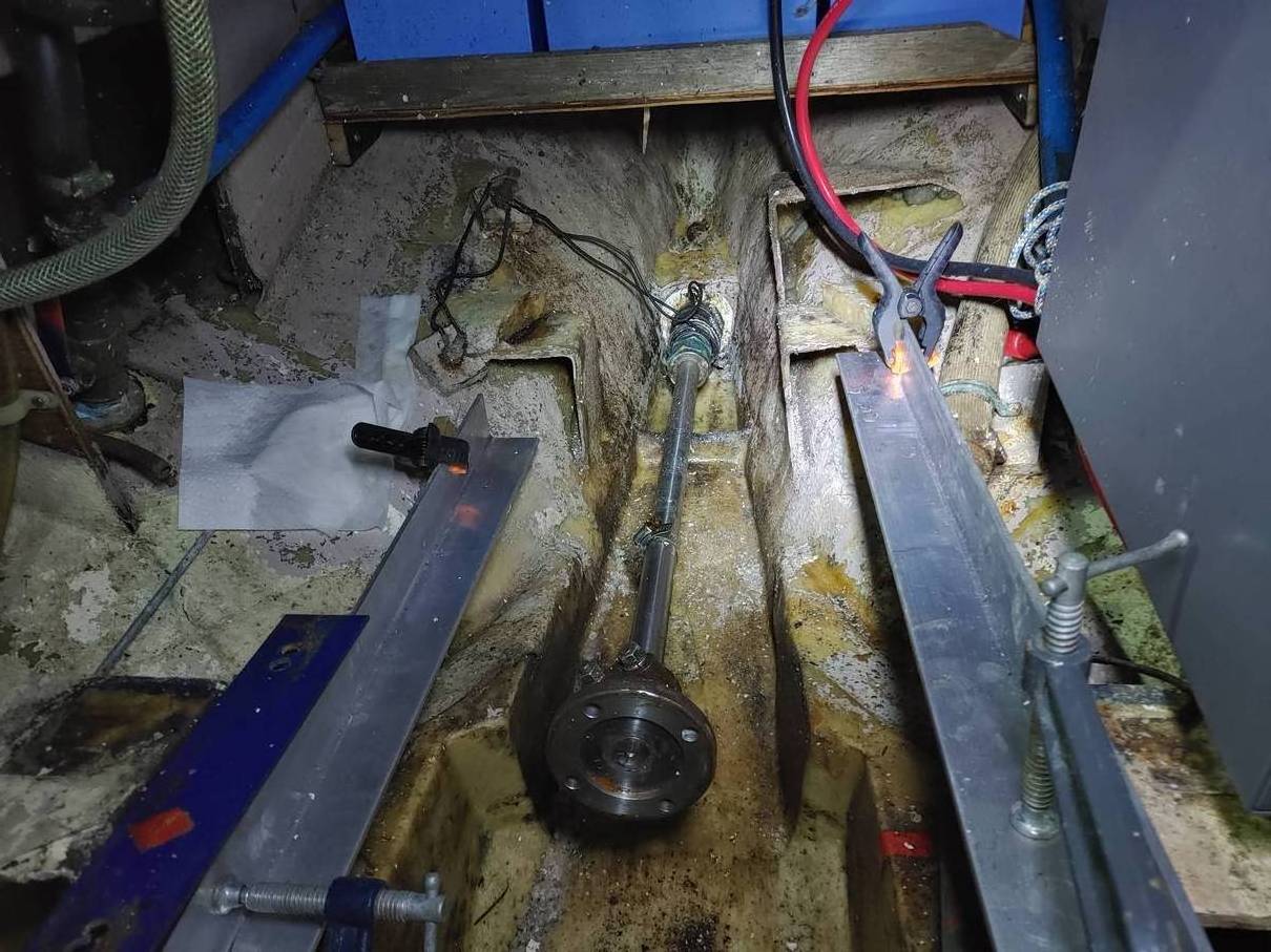
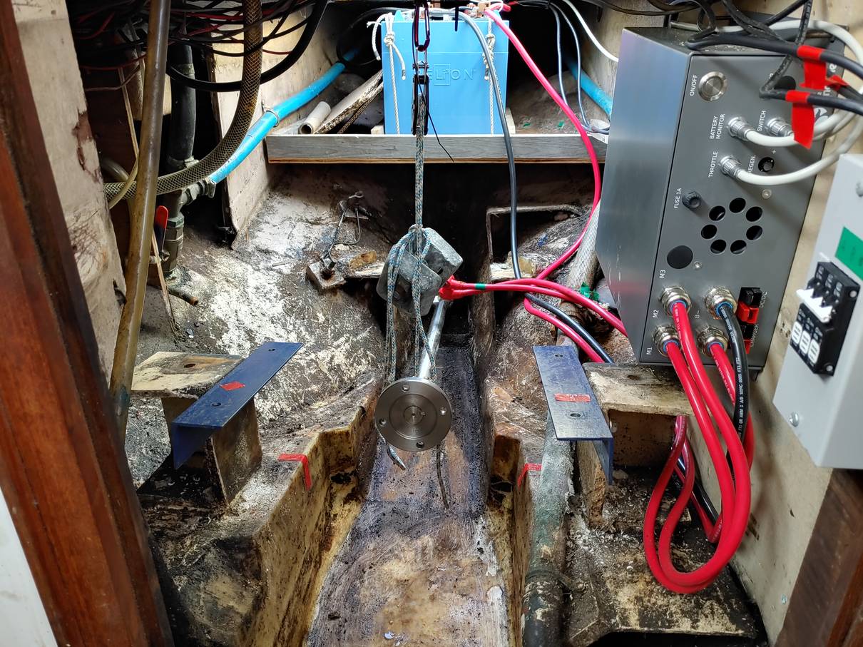 Setting up to align the motor. The weights and pulley are supposed to
balance the unsupported weight of the prop shaft.
Setting up to align the motor. The weights and pulley are supposed to
balance the unsupported weight of the prop shaft.

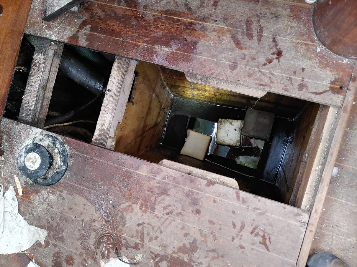 Cleaning old oil from the bilges with slices of plastic foam
The Watermota had been leaking oil for some time (years). I hadn't realized quite how much. Most of the oil was in the bilge under the engine (the oil pan overflows with rain water that gets past the cockpit floor seal, and weepage from the stuffing box, carrying oil with it).
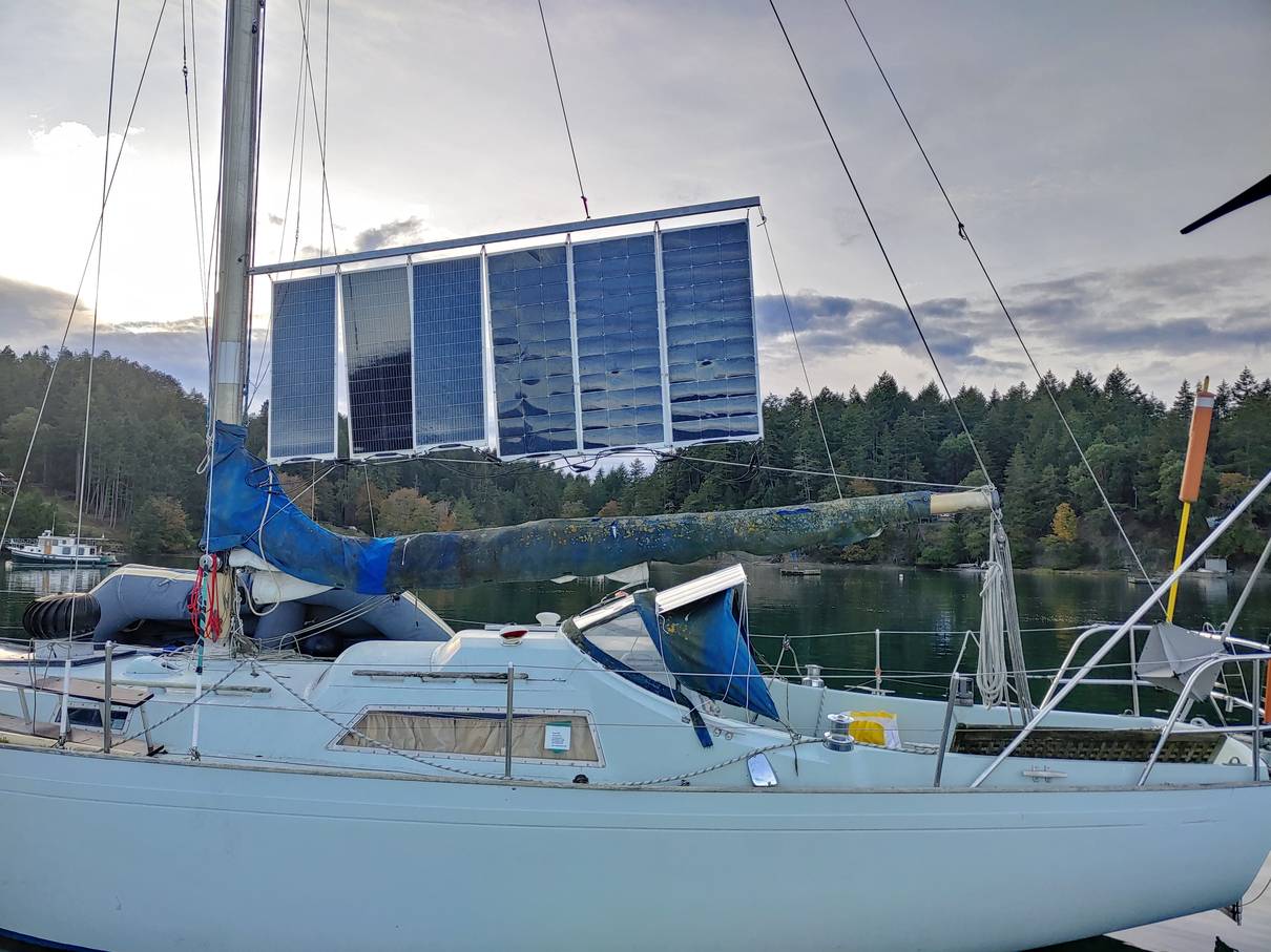
 Panels mounted on auxiliary track - I can hoist the panels and the sail
at the same time.
Panels mounted on auxiliary track - I can hoist the panels and the sail
at the same time.
I've ordered material to fit a second track on the starboard side, so I'll be able to collect power sailing east as well as when sailing west.
The Great Battery Connection Question - my investigation into whether I had connected the batteries "wrong", or whether there was a better way.
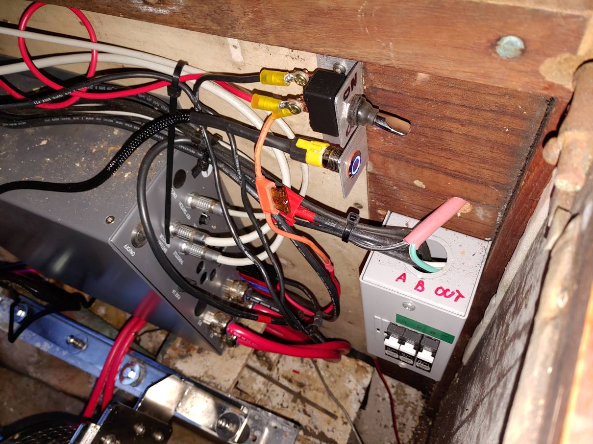
I'd been thinking about the possibility of flying the two rows of solar panels facing in different directions, so that I'd get some sun from both port and starboard as the boat turns. I fitted a couple of blocking diodes in series with each string so that the panels on the sunny side won't discharge through the ones on the shaded side. I'm not entirely sure they are necessary, but they can't hurt.
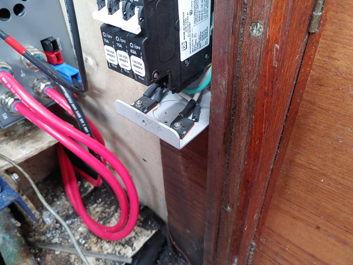 Blocking diodes in the circuit breaker box. Also shown are the Anderson connectors on
the motor controller.
Blocking diodes in the circuit breaker box. Also shown are the Anderson connectors on
the motor controller.
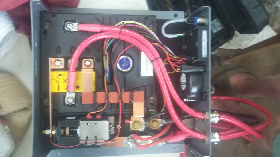 Inside the motor controller - another motor controller
The extra connectors seem to be connected to the battery cables, but the other side of the shunt. That means that the monitor will know about current that flows through them.
I had had the solar charge controller connected directly to the battery bank. That worked, but the monitor didn't know the batteries were being charged. Clearly the thing to do was to connect the charger to the "charger" terminals, but I didn't know what the connector type was, though it looked vaguely familiar.
A Google reverse image search with the hint "connector" suggested that they were an Amp or Anderson connector. I ordered some, based on images in an online catalog, but didn't check the dimensions. They were much too small. More online searching found a blog from another Thoosa user in 2009 saying that they were 75 amp Anderson Powerpole connectors. I ordered a couple of pairs, but the catalog showed them in the wrong colours, so I have blue instead of black. Never mind, it works. Now with the solar controller connected that way, the monitor shows the batteries charging as well as discharging, and its "dead reckoning" scheme of estimating battery status has a chance of working. The other thing I needed to do was to configure the monitor with the correct amp-hour rating of the battery bank, which is 120Ah (30Ah each). I had previously set it to 60Ah when I had just 2 batteries, so it was reading low.
I'd been thinking about how to improve on the wooden spar (with steel eyebolts) as a support for the panels, when I spotted a telescopic boathook in the chandler's. I bought that with a view to hacking it up. After a few hiccups I ended up with something that I hope will survive a while in service. Instead of the length of cord securing the wooden spar to the track slider, I have a stainless shackle, with stainless loops pop-riveted to the aluminium. It will no longer telescope shut, but it will come in half for easier storage.
I've decided to replace the current halyard and bridle on the spar (the "head" of the "solar sail") with a throat halyard and a peak halyard (using gaff-rigged terminology). The peak halyard will be the current halyard to the top of the mast, while the throat halyard will go to a block at the top of the solar sail track. I'm waiting for more track material before getting my big ladder aboard.
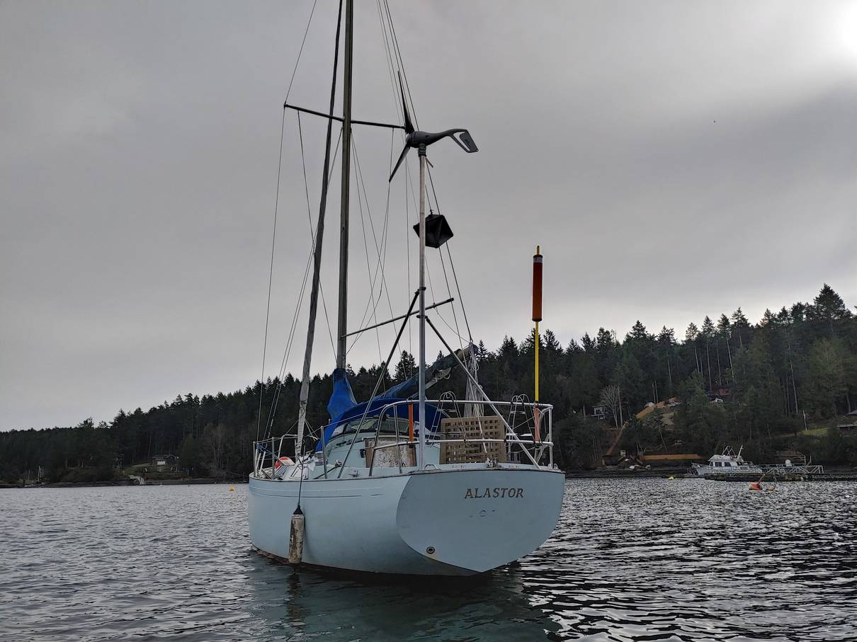
 Maiden electric voyage - Princess Margaret Marine Park on Portland Island
About 14nm each way. On the way out I had some sun but not much wind in the morning, setting out from Mayne Island, and hoisted the solar panels, motoring slowly so as not to use much more power than I was generating. In the afternoon the wind came up so I sailed for a while, anchoring off Portland Island. On the return trip, Alastor was finally re-launched about 4:30pm so I sailed to Portland Island again. The next day was raining with very little wind (or sun) so I motored essentially the whole way, at just under 2kt, arriving with something like 60% charge left. The tide in the Horton Bay narrows was against me so I cranked the throttle open a bit to get 2kt over ground, maybe 4kt through the water, for a few hundred metres. I was intending to do some speed trials to get a power curve, but it was too miserable in the rain.
While at the boatyard I took the opportunity to pressure-wash the interior of the engine compartment and bilges. 40 years worth of gunk, and there's still a bit of oil draining down from somewhere.
I also fitted a pair of Anderson connectors to the GX4820 charger, so I could plug that in to shore power and charge without taking the cockpit floor up.
Another issue that came up was that something in the motor controller, maybe the monitor itself, is showing a parasitic load of about 200mA when the controller is "off". That's almost 5Ah, or 4%, per day. I found a battery switch in a secondhand store and fitted that in series, so I can disconnect the batteries instead of raising the cockpit floor and turning them off individually. One problem with that - if they aren't full, the monitor loses track of the charge state for its dead-reckoning.
 Glueing new rear mounts.
I salvaged a couple of the big chunks of GRP I'd pulled off the old rear mounts. I then expoxied them to the hull, using the new rails as a guide. The idea was to glass over the joints for a bit more strength. Which I did. Unfortunately, I didn't use quite enough hardener for the temperature. Also it rained that night, and some water got in through the cockpit floor (not bolted down as I need access to the batteries). That wetted the new glass, so a couple of layers never set. I've pulled them off. The lower layers seem OK but I'm waiting for a bit dryer weather before sanding them and trying again.
I found the stern navigation light wasn't working. It seems that the engine block was used as a common connection point for a lot of 12V ground connections, not all going to the same point, so when I pulled the engine out I'd cut the 0V wire to several services. I thought I'd found them all, but must have missed the one to the stern - one of a number of black wires disappearing into the original black-taped wiring harness.
I haven't done much since the last update; but in case anyone reads this:
I'm picking up a replacement battery tomorrow, along with a CANBUS monitor and hopefully a remote switch. That should show me the actual charge state of the battery bank, rather than relying on the "guessometer".
I'm planning on getting a Primus wind turbine, probably this one to augment the solar panels. That will go on a 9 foot pole at the stern. I'm reluctant to leave the panels hoisted when I'm not around, but the turbine should withstand a good blow and be able to recharge the batteries in anywhere from a day to a week, according to my modelling.
The new coupling flanges got really rusty without a protective layer of grease and dirt, being just untreated steel. I pulled them off and sprayed them with an anti-rust paint.
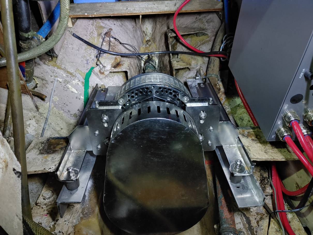 Mk III motor mounts, aluminium with rubber isolating mounts.
The rails are about 3cm lower to accomodate the rubber mounts. That meant the port side mount hit the copper pipe for the bilge pump, so I turned it upside down and trimmed some metal from the side to avoid the rail on the motor from hitting it.
I will probably order those. Meanwhile I fitted a set of bolts with rubber sleeves that prevent the motor moving fore and aft. They also have top washers as a fail-safe against mount failure.
 Mounts with limiting bolts
 The ReLiOn "fuel gauge" showing total battery capacity
Estimates of available solar power based on the angle of the panels to the sun.
 Port and starboard tracks
Added a starboard track (for sailing east with the sail up). I forgot to leave space for
the end stop so I had to cut a quarter-inch off the bottom of the track.
I also forgot that the uphaul can't go through the sail, so I'll have to add another block at the top
of the track.
Polar Battery got me the CANBUS "fuel gauge" for the batteries, which works well (showing the actual combined charge state of all 4 batteries). But they didn't get the switch; not in their inventory system or something. I'd asked again back in December, but last week they still had nothing. They say they can't even get batteries. Supply chain problems, or merger/acquisition issues with ReLion maybe. I tried shotgun emailing multiple ReLion distributors. One in Florida took my money and say they can get it. Also, the wind turbine is on its way.
The wind turbine arrived. I had thought I could use my old catamaran mast for the turbine, but it's too narrow. I found a place on Vancouver Island that sells all kinds of metal pipe and extrusions online so I ordered the exact type recommended by the turbine manufacturer and drove over to pick them up. Much quicker and easier than I had expected.
The turbine sits on a 2 inch diameter metal pole. They recommend 9 feet tall to keep the blades well clear of any crew - apparently they can slice your head open if you get too close when it's spinning. The mounting kit includes stainless fittings for two 1 inch diameter stays, and a bottom mount for the pole, all with rubber anti-vibration mounts. They are all designed to mount on a more-or-less flat deck - there is only one degree of freedom in the deck fittings so you can't for instance mount them on a vertical surface that isn't in line with the pole.
Originally I thought to mount the turbine pole and stays to the top edge of the coaming. Two problems - the brackets were too wide so I'd have to cut them down, and it is virtually impossible to fit a nut up inside the coaming to secure the bolt (though I could have tapped a hole, it would not be so strong). I thought to bolt them to the outside of the coaming, but the degrees-of-freedom issue stymied that. So I ended up using the deck area outside the coaming, cutting down a couple of brackets to fit.
I ran the wires for the turbine into the stern coaming and then along the back of the locker to end up in the engine compartment. The turbine feeds one of the auxiliary connections on the motor controller so that the charging current will register on the motor display. I'd bought a few small Anderson connectors in error, so I used those to connect the pigtail leads on the turbine to the longer leads in the locker. Mounting the turbine on the pole was a bit tricky. Normally you'd secure the bottom of the hinged mount to the pole, mount the turbine on the pole, and pivot it up into position. I couldn't do that because the pushpit and coaming are in the way, so I had to do it outside the rail with everything secured by safety lines, and pull the slack wire through before raising the pole. It wasn't particularly heavy.
 Complete turbine assembly
See the photos page for pictures of the stay mounts.
Motor controller when OFF - 15mA
Motor controller when ON - 28mA
Motor ON - 450mA ("ignition switch" on, contactor closed, motor not running)
Motor controller when OFF, motor monitor unplugged - 13mA
ReLion battery monitor - 21mA
Wind turbine ON, but not turning (below 7mph per the manual) - 10mA
So unless there's enough wind to produce power, leaving the system turned on
consumes about 46mA (about 2W), about 1% of capacity per day.
It's not immediately clear how much wind there is in the harbour; the nearest weather station is in a more exposed location. I reconfigured the wiring so that the turbine is connected directly to the battery, and the battery monitor is downstream of the main disconnect switch. So with the batteries on, I should lose only 10mA (plus whatever self-discharge current the batteries themselves have).
I'd calculated the expected energy from the turbine ("Breeze" model) based on historic weather data from the nearest weather station. It turns out that Alastor is a lot more sheltered in Horton Bay than the weather staiton, so my calculations are essentially useless. See turbine curve
 InSight battery switch and turbine switch
When I hooked it up with the splitter cable, the fuel gauge quit working, and then stayed not working when connected the original way. It's working again now. More fiddling around required making sure the connections are good, I suspect.
After checking the various discharge currents in March, I re-read the battery manual. There in black-and-white it says that the battery will self-discharge quite rapidly when on - 10% loss in 3 days, then 7% loss in the next 3 weeks if it enters sleep mode - compared to 3% loss per month when off. So the discharge due to the instruments is minor - it's mostly the battery internal BMS that's to blame. Accordingly, I moved the wind turbine connections back to the motor controller, so that the monitor would show the charging current.
After I'd connected everything, I turned the wind turbine on, and it promptly blew the fuse. It blew a replacement fuse, too. I left it and returned to the problem a few weeks later. I initially assumed that there was a short in my wiring, but after lowering the pole and removing the turbine, it was apparent the short was in the turbine itself. Back home I could see that I'd trapped one of the cables and cut the insulation when I'd originally assembled it, but one cut does not make a circuit. I sent the turbine back for repair. The manufacturer found that one of the diodes had failed. They also found the cut insulation, so I had to pay for the repair. At the time of writing, I haven't got the turbine back, but they say they will return the original circuit board so maybe I can find the cause. One possibility raised was "an inductive surge". That seems unlikely, but I did remember that I had accidentally shorted the input with my meter checking the voltage. I'm going to fit a transient suppressor to the turbine leads, which can't do any harm.
I also found mention of a CANBUS protocol specification in the battery manual, which I was able to find online. I bought a CANBUS USB interface on Amazon - another item with no proper instructions. If I can get that working on a laptop, I ought to be able to read out individual battery parameters and status, rather than just a combined percentage charge on the "fuel gauge".
I got the repaired turbine back from Primus, and it sort of works. The light comes on, and when the switch is not set to "off", i.e. shorted out, it spins if there's some wind. However, per the turbine curve, it takes a lot of wind to actually produce power. I put an ammeter in series with the turbine, and sometimes see it generating 100mA or more, and very occasionaly over 1A. I.e. over 50W.
In August 2023 we had a friend visiting, and intended to take her out on Alastor, but somehow that never happened. Then we got Covid, and I found I had CIDP (a neurological disease affecting my mobility). Meanwhile I'd left the solar panels in place assuming we were going to sail. There was a windstorm in October that broke some of the clips holding the panels in place and I lost about four overboard. My daughter tried diving to see if she could find them, but no luck. So I needed to replace them. Unfortunately the distributor I had bought them from no longer carried flexible panels, and the manufacturer no longer made that model, or that exact size. So I bought six new panels that are slighly smaller but give the same power.
I also replaced the original spar, made from an extending boathook, with a rectangular section aluminium extrusion from a metals distributor. That's stiffer and does not bend. I had noticed that the travellers for the panels sometimes got caught on the mainsail runners, so I filed the edges down to put a chamfer on them.
New spar and panels. Now with 12 panels total.
I also replaced the orignal cheap aluminium carabiners (sold as keyrings) with proper stainless steel shackles. Bought straight from a marine chandlers those would have been fairly expensive, but I found a good price online ; I need 36 to deploy all 12 panels facing the same way. I find it easier to leave the panels configured double-sided as in the picture; it's not so efficient but they generate power on either tack and have less windage, so are less likely to be damaged if the wind gets up.
In 2024 I noticed that the batteries were reluctant to turn off, meaning that they were running down due to the self-discharge current unless the solar panels were conencted. The switch worked to turn them off, but then they'd turn on again by themselves about 30 seconds later. I tried putting four panels flat on the coachroof, but with shading from the boom and a lack of sun in winter they weren't enough to keep the batteries charged properly.
In 2025 I bought a small inverter generator to charge the batteries if there's no sun. That powers the 120V battery charger to charge at about 20A, and isn't too heavy or noisy. Alastor is currently on a mooring, and while a new dock was constructed nearby, there's no power or water there.
In August 2025 we sailed across to another island for a meal, and back, after waiting for the tide in the morning. We got back to the harbour with about 25% charge showing on the meter, but the motor suddenly died and the meter nosedived to zero. I was able to grab another mooring and run the generator to recharge.
I've brought the batteries home to test on the bench. They are still not turning off properly, and not all seem to respond to the external switch.
I tried using the USB CANBUS interface to monitor the batteries, but it didn't work. I bought a second different interface and while the two interfaces talk to each other, I still can't collect data from the batteries. However, I can see the CANBUS waveforms with an oscilloscope, and the ReLion battery monitor works to display the state of charge. That is sometimes odd - the batteries are nominally 30Ah each, but the monitor shows 100% charge and 90Ah total. There's a button sequence to reset the battery management unit, but that didn't help with the batteries turning back on, and isn't clearll helping with the odd state-of-charge readings.