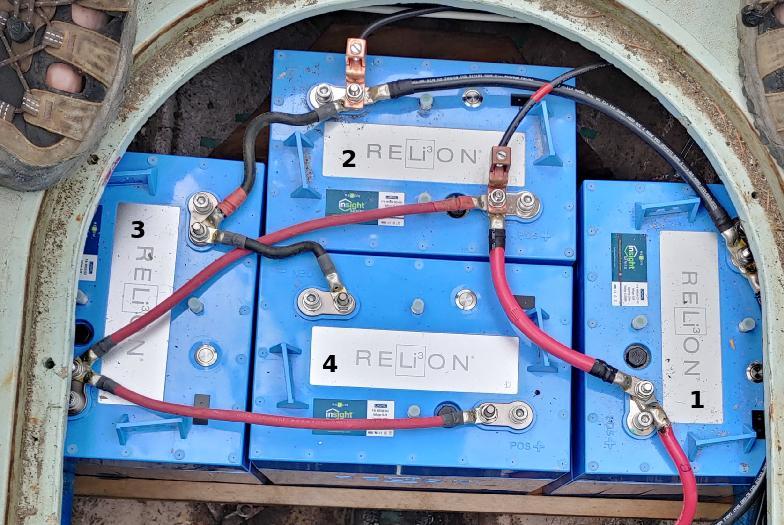
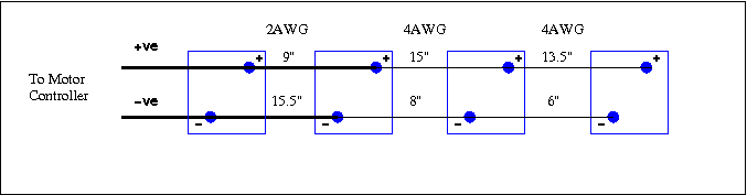
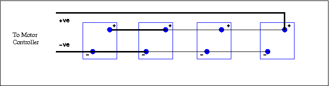
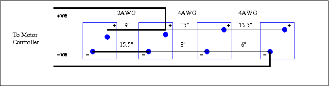
The idea there was to keep the wires between the batteries short, and use thicker wire for the connections that carry more current.
When I posted the picture online, someone pointed out that I should connect the load diagonally across the battery bank. Which it turns out was suggested in the battery handbook, and in various texts online. The optimal solution to equalize battery current in a battery bank is to have a pair of thick copper busbars, and lead equal lengths of cable from each battery terminal to those. But the diagonal connection is given as an alternative.
So of course I had to run a simulation, and measure voltages in situ, to see if that really was better. It is, somewhat, but it's not the best solution.
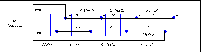
I disconnected all the inter-battery connections and strung them out in series, driving the motor at 20A from one battery, then measured the voltage across each segment, getting values of the order of 5mV. That correlated fairly well with calculated values for each length of wire.
| Link | Name | Length | Gauge | Resistance | |
|---|---|---|---|---|---|
| Calculated | Measured | ||||
| 1-2 +ve | R1112 | 9" | 2AWG | 0.117mΩ | 0.143mΩ |
| 2-3 +ve | R1213 | 15" | 4AWG | 0.311mΩ | 0.348mΩ |
| 3-4 +ve | R1314 | 13.5" | 4AWG | 0.280mΩ | 0.312mΩ |
| 1-2 -ve | R2122 | 15.5" | 2AWG | 0.201mΩ | 0.205mΩ |
| 2-3 -ve | R2223 | 8" | 4AWG | 0.166mΩ | 0.164mΩ |
| 3-4 -ve | R2324 | 6" | 4AWG | 0.124mΩ | 0.128mΩ |
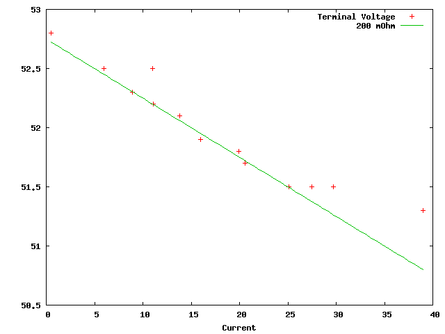
The battery manual quotes the internal resistance as <150mΩ. I drove the motor at different RPM and measured the voltage at the battery terminals, using the current shown on the motor controller display. That gave me a resistance of about 200mΩ, which I used for the simulation runs. That's something like 500 times greater than the cable resistance, so I'm wondering if the cables make any practical difference at all. When I measured voltage drops across the actual cables with the motor running, I got inconsistent results; I believe that the battery management units in the different batteries (linked by CANBUS, not fitted in the photo above) were balancing the battery charge states.
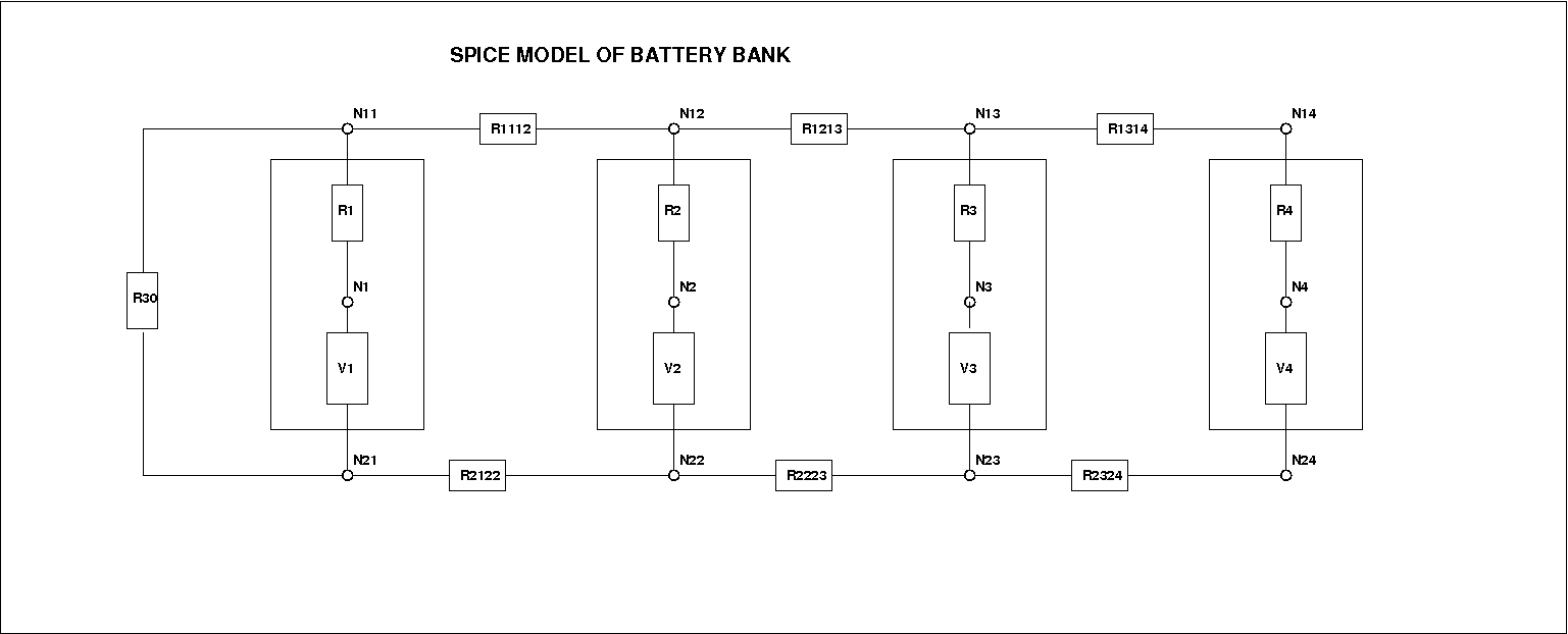
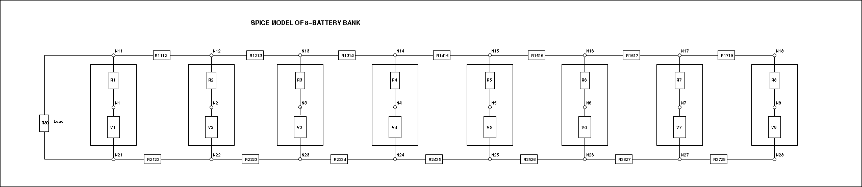
I ran simulations using ngspice, a simulator based on the original Berkeley SPICE3.
Since I have different lengths of cable between the batteries, in two different gauges, the cable resistances are all different. I simulated a load connected across all possible combinations of battery terminals, and found a solution that was better (less variation in battery current) than either my original install, or the suggested diagonal connection.
As initially installed, batteriesA20.cir, load at one end (nodes 11-21)
| Battery | Current |
|---|---|
| 1 | 5.209 |
| 2 | 5.184 |
| 3 | 5.160 |
| 4 | 5.149 |
As suggested, batteriesA20z.cir, load connected across a diagonal (nodes 14-21)
| Battery | Current |
|---|---|
| 1 | 5.176 |
| 2 | 5.164 |
| 3 | 5.171 |
| 4 | 5.190 |
Optimal as calculated with cables as installed, batteriesA20z5.cir, load across middle (nodes 12-24)
| Battery | Current |
|---|---|
| 1 | 5.173 |
| 2 | 5.181 |
| 3 | 5.174 |
| 4 | 5.176 |
| Battery | Current |
|---|---|
| 1 | 5.178 |
| 2 | 5.174 |
| 3 | 5.173 |
| 4 | 5.178 |
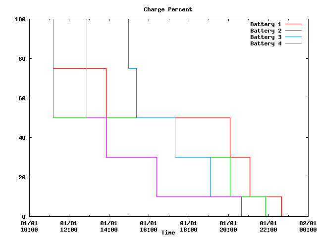
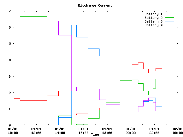
All this effort balancing battery currents may be entirely moot; experimentally the discharge currents are all over the place. One or two batteries discharge substantially with no current taken from the others, then the others discharge. I had noticed uneven voltages across the interconnect cables when installed on Alastor, and pulled them all out to test them at home. I connected all four in parallel in a star configuration, using equal lengths of 8AWG cable as a current shunt. I then used the batteries to power a couple of 120V space heaters (at 50V, but they're basically resistive). The heaters took 8A from the battery bank. I then measured the volts drop across each shunt to get individual currents, and monitored the state of charge by tapping the buttons and looking at the LEDs (the batteries flash red/yellow/green patterns to indicate 0,10,30,50,75,100% charge).
I contacted the battery manufacturer; this behaviour may be normal and doesn't really matter. There was another issue with one battery - it will not charge with the mains charger when connected in isolation. They're going to exchange it. This may solve another problem related to the remote power switch (on order, not yet arrived). Apparently only newer versions will work with the switch, but only one in the bank has to be new. Another weird issue is that if the batteries are turned off, turning any one of them on will turn on the rest. But if one of them is turned off, unless they are all turned off manually within 15 seconds or so, not only will the others not turn off, but the first one will turn itself on again.
8batteries-s.cir, load at one end (nodes 11-21)
| Battery | Current |
|---|---|
| 1 | 12.61 |
| 2 | 12.44 |
| 3 | 12.29 |
| 4 | 12.17 |
| 5 | 12.07 |
| 6 | 12.00 |
| 7 | 11.95 |
| 8 | 11.93 |
8batteriesz-s.cir, load across diagonal (nodes 18-21)
| Battery | Current |
|---|---|
| 1 | 12.27 |
| 2 | 12.19 |
| 3 | 12.15 |
| 4 | 12.12 |
| 5 | 12.12 |
| 6 | 12.15 |
| 7 | 12.19 |
| 8 | 12.27 |
8batteriesz2-s.cir load across half diagonal (nodes 13-26)
| Battery | Current |
|---|---|
| 1 | 12.15 |
| 2 | 12.18 |
| 3 | 12.22 |
| 4 | 12.20 |
| 5 | 12.20 |
| 6 | 12.22 |
| 7 | 12.18 |
| 8 | 12.15 |